2 DOF Articulated Pen Plotter
Beng Mechatronics Graduation Project
Gregory Bourke
[Blog under construction]
[Blog under construction]
 |
Synopsis
This project was a 4th year project undertaken to demonstrate the application of scientific and engineering knowledge gained through the duration of the B(eng) Mechatronics degree at Nelson Mandela Metropolitan University, Port Elizabeth, South Africa.While research was undertaken to better understand the concept of simple robotic arm control, it was noted that a single location with all the information that was needed condensed into a neat blog or paper was not found. This blog will serve to best convey the concepts used to control a simple 2 DOF G-Code pen plotter robotic arm and also outline the mechanical design process, mathematical modeling, electrical design and implementation.
The project involves the design and implementation of an articulated robotic arm with 2 degrees of freedom (DOF) capable of plotting G-Code commands onto a flat surface with a maximum size of a standard A3 (420mmx297mm) area. The project consists of a number of stages, namely conceptualisation, system design, component selection, mathematical modelling of the arm, coding of the control hardware, implementation of control hardware, performance analysis and conclusion.
An Arduino Uno was chosen as the platform used as the control hardware used on which the control of the arm was implemented, using inverse kinematics.
Performance and test results show that a robotic arm which is capable of plotting commands streamed to it via the user from a program specifically developed to control the robot arm was achieved. The robot arm is able to successfully plot circles, lines and font paths generated by a font path generating program.
 |
A photograph of a font path plotted by streaming GCode commands to the pen plotter
|
Introduction
This blog serves to compress the final report into a blog which will discuss the final design of the project and a detailed view on how the system requirements were achieved through implementation. The blog will skip in-depth comparison between concepts, and move directly into the final design.
A robotic arm is a mechanical arm which has similar functions to a human arm and in the case of this project (and usually), is programmable. Robotic arms consist of a series of connected links of either revolute or prismatic joints which form a kinematic chain. The end of the kinematic chain, termed the end effecter, is where the tool is located and is analogous to the human hand. Revolute joints allow rotational motion about an axis, while prismatic joints allow linear translation along an axis
Robotic arms are used extensively in
industry from a simple robotic arm which performs pick and place tasks to the
most complicated such as a 6 DOF articulated arm capable of a variety of operations
programmed using inverse kinematics, velocity kinematics, trajectory planning
and dynamic modelling. Robotic arms are used because they are versatile and
can be reprogrammed to perform any task necessary within its capability and
will faithfully carry out that task until they are reprogrammed or instructed to
stop. Typical robotic arm operations include pick and place, welding,
inspection, assembly and painting. These operations can be achieved with high
speed and precision (Spong, Hutchinson, &
Vidyasager, Robot Modeling and Control) .
The design and implementation of a robotic
arm is an ideal endeavor to demonstrate mechatronic capability as it is a
complete integration of mechanical design, computer science and electronics. The
purpose of this project is to demonstrate the application of mechatronic
ability by applying mechatronic skills and know-how to solve a mechatronic
problem.
There have been many designs of 2-DOF
robotic arms and a quick search on the internet proves this. They all vary in
construction and size and what their final goals are. Most of the systems
found on the internet, in the case of typical graduating projects, are 2-DOF
arms programmed using inverse kinematics or controlled by external input such
as a potentiometer (Ouyang, 2013) , or similar type of master/slave
interface. They are built using a mainly servos and stepper motors for
actuation.
Mechanical Design
The mechanical design of the system includes the arm construction and the reduction gear couples, platform holding the base of the arm as well as the motors.
Arms
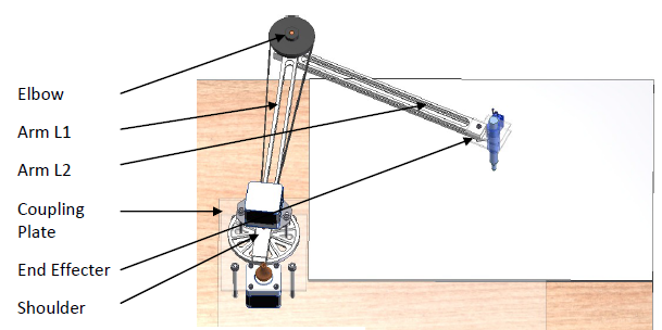
The arms needed to be light weight in order to minimise the inertial load reflected to the motors through the coupling systems but also strong enough to hold any other forces in the system without much buckling, bending or large deflection due to weight. The robot consists of 2 arms, L1 and L2. For reference, arm L1 is coupled to the shoulder drive motor, while arm L2 is connected at the elbow, to which the end effector (the pen) is connected.
 |
| Mechanical nomenclature |
The length of the arms was designed such that the robot could reach the farthest and closest corner to the robot base.
Arm L1
Design of the arm L1 was influenced by the choice of synchronous belt and pulley’s (discussed in section 4.1.3 Gear Couples) where the distance from the shaft holes were set such that they are the same as the centre distance for the synchronous belt and pulley system. This was to allow the elbow motor to be placed directly above the shoulder shaft.
Electrical Design
..To Come..
Mathematical Modeling
Inverse Kinematic Equations
Placing the robot base at its position depicted below simplifies in design of the system such that the arm will only ever be in the “elbow up” position and never in the “elbow down” position. To solve the angles the arms need to be at in order to achieve a desired location of the end effector (pen), inverse kinematics is used. Inverse kinematics calculates the required angles of the arms, theta 1 and 2, in order for the end effector to reach its desired coordinate point.
 |
| The arm in the elbow up position |
 |
| Diagram of system |
noting that
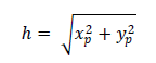
and using the law of cosines

Substituting a for h, b for l2, c for l1 and A for (pi - theta2) and solving for theta2 yields

to find theta p, atan of the new coordinate was calculated

to solve for alpha, the law of cosine was again used. Substituting all the relevant variables and solving for alpha yields

noting that theta 1 is simply the addition of theta p and alpha, theta 1 is calculated by

Thus, the values for theta 1 and theta 2 which are required for the end effector to be at a desired location can be found. These equations are later implemented in the Arduino code along with other equations (discussed later under the main/initialise code segment ) to achieve the desired number of steps for the stepper motors in order to reach a desired location.


 It is clear from these equations, that the torque is dependent on the acceleration/deceleration as well as the mass, lengths of certain mass moment points away from other points and inertia of the arms. The construction and assembly of the parts on the arms make it near impossible to calculate the moments of inertia analytically. To approximate the inertia's IA and ID , AutoCAD inventor was used to model the arms by assigning materials to known components, such as the aluminium arms and shafts, and by manually inputting the weight of components which are constructed of a variety of materials. This is an approximation since Inventor will assume uniform mass distribution of parts such as the 9g servo, which is not entirely correct. But as stated, it served as an approximation. The mass of each arm was also read from Inventor, but the arm configurations were also weighed to double check. The results from physical weighing and approximation using inventor coincided.


 The result shows that the torque to accelerate each arm is extremely low, and this is attributed to the fact that the motors need only to move the arms in the horizontal plane. If the arms were to be moved in the vertical plane, the Lagrangian would include potential energy, and the motors would have to apply torque to rotate the weight of the arms, and not just the inertia of the arms.
Dynamic Equations of Motion
With the use of stepper motors, it was imperative to calculate the maximum acceleration the steppers could handle according to their available torque Vs. the load they were driving.
Calculation of the torque required to accelerate the arms is not simply a case of applying the torque equation , but is rather a dynamic problem requiring a dynamic solution. Energy methods utilising the Lagrangian was used for this purpose.
The following equations describe the torque at each joint, calculated using the Lagrangian of the system. The derivation is mathematically intensive, and thus the derivation is shortened as much as possible.
The lagrangian is calculated as the difference between kinetic and potential energies of the system
Thus the kinetic and potential energy of the system need to be computed. The velocity of the center of arm L2 is found by differentiating its position
Where lm2 is the distance from the axis of rotation to the center of mass for arm L2. The total velocity of the center is then
where
The following identities are used to simplify the addition
and
which yields
The rotational kinetic energy of arm is calculated using
It is important to note that IA is the inertia of arm around the axis of rotation of arm L1.
The kinetic energy of arm L2 is the summation of its rotation energy due to its own rotation, and the rotation and linear velocity imparted on the arm from the rotation of arm L1 and is calculated using
Where ID is the moment of inertia of the arm at its mass centre, or point D. The total kinetic energy of the system is then
Multiplying out the brackets and simplifying by factorizing out common time differentials of both angles yields
The equation for potential energy is given as
Since the arms are in the horizontal plane and gravity will not cause the arm to move, the potential energy of the system is always zero. Thus, the Lagrangian is
Thus the equations of motion are given as
Which yields
The following values were given from Inventor:
Substituting these values into the equations for the torques at each joint yields
The Stepper motors are set to accelerate at a rate of 500 pulses per second per second. Due to the microstep ratio, the motors step at 0.255 degrees per pulse. The accelerations are also reduced by ratio of the gears
Noting that these torques are the torques to accelerate the inertial components of the arms only, and not the inertia of the motors rotor, the torque required from each motor to accelerate the inertial load and the inertia of its rotor is then the summation of the torque required to accelerate its own rotors inertial load and the torque required to accelerate the arms reduced by the gear ratios, as follows
IT Design
There are two parts of software for the
robot arm - the program which is loaded onto the controller platform (Arduino)
as well as the software used to communicate with the robot arm from a computer.
A Microsoft Windows executable program was designed to stream G-Code commands
via serial communication to the Arduino and is called the robot control
program.
Setting the motors to maximum speed from
rest could result in the motor being unable to move the load and therefore
skipping steps, or cause damage to the plastic gear used in the shoulder
coupling system which are both extremely undesirable. To curb this, an
acceleration profile for the stepper motors was needed and was implemented by
the addition of the AccelStepper Arduino library which is based on calculations
derived by David Austin (Austin, 2005) . The AccelStepper library improves on
the standard stepper library in the following ways (McCauley) :
- Acceleration and Deceleration support
- Supports independent concurrent stepping on multiple simultaneous steppers
- Non-blocking API functions
- Support of 4 wire steppers
- Slow speeds are supported
- Compatible with the EasyDriver
Thus the AccelStepper library will be used
to control the stepper motors.
Arduino Software
- Main/Initialise
- Loop
- To Point
- Park
- G-Code Implementation
- Circle
Main/Initialise
The main/initialize segment contains all necessary
functions and is where the setting up of the I/O’s, global variables, defining
of steppers, servos and inclusion of libraries occur. Two libraries are
included into the sketch, namely the AccelStepper and Servo library.
Global variables are initialised to store the current
angles of each arm, as well as the current x and y position of the arm respect
to the robot frame. The home position can either be set at the top left hand
corner or in the middle of the canvas, using the robot control software (see 4.3.2
Robot Arm Control Program).
For example, Home is defined at the middle of the canvas with the coordinates
(210,149). This translates to the following set of values which were used to
define the current x, y, theta 1 and 2 values
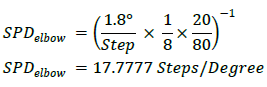
A SPD (Steps per Degree) variable is defined for each motor in order to determine the number of steps each motor is required to move per degree. The SPD for each motor is dependent on the step angle, gear ratio and microstepping ratio of the drivers for the motor according to the formula

Where np is the number of teeth on the pinion gear, nd is the number of teeth on the driven gear and a microstep ratio of 8 microsteps per full step. SPD for the shoulder is calculated by substituting 12 and 145 for np and nd respectively

For the elbow SPD, substituting 20 and 80 for np and nd respectively yields
- CurrX = 265 (CurrX with respect to robot frame, 210 canvas frame)
- CurrY = 137 (with respect to robot frame, 149 canvas frame)
- theta1= 84.67 (CurrAngle1, measured positive, anticlockwise)
- theta2= 113.55 (CurrAngle2, measured positive clockwise)
A SPD (Steps per Degree) variable is defined for each motor in order to determine the number of steps each motor is required to move per degree. The SPD for each motor is dependent on the step angle, gear ratio and microstepping ratio of the drivers for the motor according to the formula
Where np is the number of teeth on the pinion gear, nd is the number of teeth on the driven gear and a microstep ratio of 8 microsteps per full step. SPD for the shoulder is calculated by substituting 12 and 145 for np and nd respectively
For the elbow SPD, substituting 20 and 80 for np and nd respectively yields
The arm lengths are also defined in the main class, as well as their squares to decrease the computational time required within the inverse kinematics calculations.
Loop
The loop function runs continuously checking the Estop, as well as checking if data is available on the serial port sent from the robot control program. After a command is performed, the Arduino will jump back to this loop, ready for the next command from the robot control program.
Once the port is open, the Arduino constantly scans the serial input buffer for available data. If data is available, a while loop reads each available character into a string (content) of length 15. This ensures the entire G-Code command is received. An if statement is implemented inside the continuous loop straight after the serial read while loop to check whether there is information inside the content string. If the content string is not a null string, the content is passed through a series of if statements, checking which code have been sent through from the Robot control software. The following are the codes which the PC software sends to the Arduino via the serial link:
- “JU” - The robot controller software has requested that the robot be jogged, up. This correlates to an increase in the CurrY position by 1.
- “JD" - Jog the robot, down – correlates to a decrease in CurrY position by 1
- “JL” - Jog the robot, left – correlates to a decrease in CurrX position by 1
- “JR” - Jog the robot, Right – correlates to an increase in CurrX position by 1
- “HO” - Set current position of the robot arm as the home position situated at (0,297)
- “H1” - Set current position of the robot arm as the home position situated at (210,297149)
- “GH” - Send the robot to defined home position.
To Point
The to point (called toPoint) function translates the required canvas coordinate to the robot frame coordinate and then calls the function (set_arm) where the mathematical calculations based on the inverse kinematics of the system are performed (See code attached as Addendum). The function receives two parameters, x and y, which are the canvas coordinates of the new point to which the arm is required to move.
The set_arm algorithm calculates the absolute difference between the current angle (stored in Currθi, where i = {1.2}) of each motor, which is the angle to which each motor needs to move in order to reach the desired coordinates from the current coordinates. This value is then multiplied by the SPD of each motor to determine the number of steps required per motor to move the pen from the current location to the new location, after which the current angle for each arm, current x and current y variables are updated.
The motor directions are decided by comparing the angles, for the shoulder motor; if the new angle is greater than the previous angle, the motor needs to rotate clockwise and anti-clockwise if the new angle is smaller than the previous angle. The elbow motor is opposite; an increase in angle requires anticlockwise rotation, while a decrease requires clockwise rotation of the motor. This communicated to the motor by sending negative amount of steps to the motor for clockwise rotation, and a positive number of steps for anti-clockwise rotation.
Since stepper motors are open loop control, there is no feedback from the stepper motors to determine whether the stepper motor has reached its destination or not. Therefore, some sort of method needs to be implemented in the software to allow the motors to reach their destination before the new set of commands is sent through. This method only considers the theoretical number of steps the motor still needs to move according to the theoretical number of steps it needed to perform, and as such, will not know if the stepper motor has physically missed a step.
A common method to allow a stepper motor to reach its destination is to simply create a delay of approximately 10ms into the function passing through the number of steps the motor is required to move, which gives a fixed time for the motor to complete its steps. If a new target number of steps is sent through after the delay, before the stepper motor has completed its previous step count, the motor will technically discard the previous unfinished steps, and perform the next step count. The delay() method is a crude, and as such was not used as it introduces jerky motion into the movement of the arm if motions are completed a considerable time before the delay was completed, as well as not being completely certain whether the motor had in fact reached its destination before receiving the new set of coordinates.
Park
Parking of the arm is achieved by simply moving the motors back to the home position, as defined by the user.

G-Code Implementation
G-Code (G programming language) is the most widely used numerical control programming language used in many implementations. G-Code is a simple language which instructs computerised machinery (the robot arm) on how to move. These commands include how fast to move, where to move to and what kind of movement it should be (G-code, 2013).
The robotic arm movement can either be rapid movement or linear interpolation. Rapid movement performs only a single inverse kinematic calculation of the joint angles required for the arm to reach the destination coordinate. In rapid movement, there is no certainty of the path taken. Performing the calculation once will allow the motors to accelerate to their maximum speeds.
Linear interpolation divides the movement into smaller steps, calculating the inverse kinematic joint angles at small intervals between start and end coordinate using linear interpolation to calculate the next sub coordinate. Since the steps are small, the arm will never fully accelerate to its maximum speed, and thus is much slower than rapid movement. The idea is shown in the image below where black dots indicate start/end points and blue dots indicate intermediate points where the joint angle calculations are performed.
 |
| Rapid movement (Left) Vs Linear interpolation (Right) |
 |
| Table of G-Code Commands understood by the controller |
The G-Code commands are sent to the robot controller (Arduino) through an open serial link between a computer and the Arduino. A robot arm control program was created to perform this task, and is discussed later. To illustrate the use of G-Code commands, the G-Code commands in the provided screenshot of the robot control software are explained:
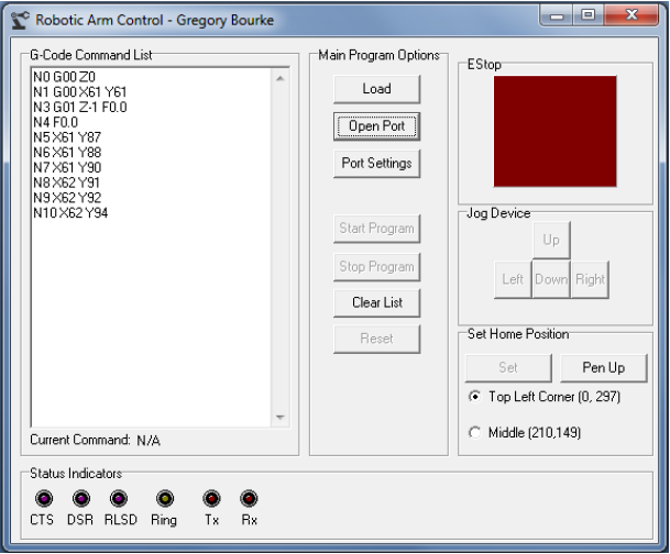
- G00 Z0
- G00 - Rapid positioning
- Z0 – Lift pen up off canvas
- G00 X60 Y60
- Rapid movement to starting position of the line to be drawn
- G00 - Rapid positioning
- X60 – Next X position (rapid positioning)
- Y60 – Next Y position (rapid positioning)
- G01 Z-1 F0.0
- G01 – Linear Interpolation
- Z-1 – Put down pen onto canvas
- F0.0 – Feed rate (for milling, ignored)
- X60 Y80
- X60 – next X position (linear Interpolation)
- Y80 – Next Y position (linear Interpolation)
- X60 Y81
- X60 – next X position (linear Interpolation)
- Y81– Next Y position (linear Interpolation)
The feed rate (F) command is not used by the robot arm since the robot has been given a set speed and acceleration profile, and thus is ignored by the G-Code parser.
The G-Code parser will execute the next command according to the last G-Code command received. For the drawing of lines and other continuous complex shapes, the program needs only to send through the linear Interpolation command G01 once – any coordinate received following the command will be executed using the last received command which is G01, Linear interpolation.
Circle
Plotting a circle is achieved by plotting the top and bottom arc half separately. In Figure 69, the nomenclature for a circle is given.
 |
| Circle plotting nomenclature |
The radius and centre coordinate (xC, yC) are required. The Starting point of the circle is then calculated by subtracting the radius from the centre X coordinate. To plot the top half, an x variable is incrementally increased by 1 from the starting x value to the finishing x value. After each increment, the corresponding y coordinate is calculated using

Each incremental x and y coordinate is then sent do the toPoint command, which calculates the required steps of each stepper motor to achieve the new desired coordinate.
Plotting the bottom half then follows and is plotted in the same manner as the top half, but with the x variable being incrementally decreased.
 |
| The code to plot a circle |
Linear Interpolation
Linear interpolation divides the linear distance from the current coordinate to the next coordinate into incremental steps. The robot has been programmed such that all incremental steps are one millimeter.
When plotting, there are cases with regards to the relationship between the new coordinate and the previous coordinate, which are:
- The new x coordinate is larger than the previous x coordinate
Example: (100,100) → (150,130)
The program incrementally increases x by 1 each step until x is equal to the required position. The new y coordinate for each x increment is calculated using the gradient between the previous and new coordinate. The coordinate at each incremental step is sent through to the set_arm function, which calculates the arm angles for the new incremental position and moves the stepper motors accordingly.
- The new x coordinate is smaller than the previous x coordinate
Example: (150,100) → (100,130)
The program incrementally decreases x by 1 each step until x is equal to the required position. The new y coordinate for each x increment is calculated using the gradient between the previous and new coordinate. The coordinate at each incremental step is sent through to the set_arm function, which calculates the arm angles for the new incremental position and moves the stepper motors accordingly.
- The new x coordinate is the same as the previous x coordinate
- The new y coordinate is larger than the previous y coordinate
Example: (100,100) → (100,130)
The program incrementally increases y by 1 each step until y is equal to the required position. The new y coordinate and the unchanged x coordinate are sent through to the set_arm function each increment.
- The new y coordinate is smaller than the previous y coordinate
Example: (100,100) → (100, 70)
The program incrementally decreases y by 1 each step until y is equal to the required position. The new y coordinate and the unchanged x coordinate are sent through to the set_arm function each increment.
Fonts
The implementation of G-Code enabled fonts to be drawn. Font path G-Code commands can be generated using DeskEngrave (www.deskam.com), which is a free desktop application enabling the user to generate and export the G-Code commands for a font path, to text file. This list is then loaded into the Robotic arm control software.
DeskEngrave accepts text from the user, as well as the origin, font size, font style and either width or height of the font – If the width is chosen as the fixed variable, the program calculates the associated height and vice-versa.
For example, the word “Test” is entered into the text box with the “Cooper” font, origin of (50, 50), and width of 200. The coordinates will be in millimeters since the robot is programmed in millimetres. Note how the Height is 0, since this will be calculated by the program. It is advisable to choose the width of the word as the user entered variable, since the length is limited to the width of the canvas (i.e. should not be larger than 420)
 |
| Test text in DeskEngrave |
 |
| Output from robot arm |
System Cost
The system cost came to a total of R 2,108.42. The material used in the construction of the arms were machined from scrap lengths of aluminium rectangular bar equal to the design parameters, and the shafts machined from lengths of scrap aluminium. The 5mm bearings were sourced from old weighing scales, and as such were also not bought. Thus, an estimate was added for if they were to be bought if possible, and their design parameters calculated accordingly.
Machining labour was also free, as all the machining was done privately.
 |
| Cost of system components |
How do u move the 2 motors at the same time though??
ReplyDeleteI used the Accelstepper library available for arduino. It allows simultaneous concrrent operation of stepper motors. I implemented it in code by polling the steppers inside a do-while loop, using the steps remaining as the stopping condition (steps remaining for each motor = 0) like this
Deletedo
{
Estop = digitalRead(sw2) ; //EStop check
if ((Estop == LOW)
{
//Poll the steppers
stepper2.run();
stepper1.run();
}
else
{
//ESTOP Routine
break ;
}
} while ((stepper1.distanceToGo() != 0) || (stepper2.distanceToGo() != 0) ) ;
This comment has been removed by the author.
DeleteThis comment has been removed by the author.
Deleteyour project is amazing, can you send me the codes used in the project? E-mail pedro795401@outlook.com
DeleteI'm having trouble figuring out how to send the G-code to the arduino, one line at a time...i mean i have tried sending a single line by typing it myself n it transfers to arduino just fine. I was also able to compare and extract data from that string. But how do I send that amount of data generated by the software?
ReplyDeleteI coded my Arduino and PC software so that there is a two-way communication between the PC and the Arduino. The PC sends a line of G-Code to the Arduino, the Arduino executes the g-code command and at the end of the G-Code execution (once the motors have reached their angles) the Arduino sends a string (just a simple "N" for "next" will do) telling the Software that the Arduino has executed the command, and is ready for the next one.
DeleteThe Software, while in run mode, is always checking the incoming serial data. If a "N" is read in from the Serial, then the Arduino has indicated that it has finished the previous command, and the PC Software can send the next one.
If you don't have a way for your Arduino to let your PC software to know when it is ready for the next command, the PC software is just going to send every single line at a MUCH faster rate than what the Arduino can execute the commands. The Arduino is MUCH slower than your PC, so the PC needs to be told when to send the next command.
Does that make sense? I Hope it did! :D
Wow...trust me when i say this...i had the exact same thought! :D
DeleteFew things though..
1st) Does the Deskengrave software generates the G-code with increments of 1 mm? or do i have to program the arduino like mentioned above?
2nd) I dont have any experience with PC software generation. So can i have the software you built?
I know i'm asking a lot of you, but i really appreciate your help :)
Well at least you are in the right track :)
Delete1) It will be interpreted however you you wish, since you are going to create the parser! I set up my g-code parser to interpret it as increments of 1mm. One thing I needed to improve/look at on my _Articulated_ system was movement of amounts smaller than 1mm but greater than the resolution of the largest motor movement resolution.. breaking the movements into floating point movements would cause an error in the Commanded Vs actual position, since the motor could only move in discrete steps. The resolution of the arm is decreased proportionally to the arm length (r*theta). - Just something to consider.
2) Sure, give me an email address. Ill send my software + arduino code. Just don't copy-paste :) read, understand, apply.
i need to your help.... i need to your software + arduino code. thank you
Deletemy email address is (abdelbaseta41@yahoo.com)
i am trying to build your project and i really apereciate the work on forward and inverse kinematics plz send me the code. antenehtdss@gmail.com
Deletethanks alot
Hi,
Deleteplease me the sofware and Code for arm .
Thank you,
mech.robo@gmail.com
Hi! please send me the software + firmware
DeleteThanks, ramiro.volt@gmail.com
Oh right..i understand. I have already written the code of divinding it into increments of 1 mm using slope method :D ...after that, now i'm gonna start the work on the ToPoint function which is to be called after each increment. In my opinion, it will be like i know the desired x and y position, and i will find the angle using the inverse kinematics solutions - elbow up. It will provide me with the respective angle of link1 and link2, and i will move the motors as currentangle-desiredangle. Both motors will have the same speed. Hope im right..?
ReplyDeletemy email address is soban29@gmail.com . You have no idea how much i appreciate it. And ofcourse, i'll understand it :) Thanks a lot mate!
Hi Soban,
DeleteCan you share the Arduino code and G Code software you received from Gregory ? It would really be helpful :) With regards :)
I am trying to build something like this.Can you please send me your code? It will help me a lot. Thank you. :)
ReplyDeleteHere is my Address : qwertykmqwerty@gmail.com
Hi! What are you building it for?
DeleteI'm trying to develop something similar too, and your code would help me a lot.
ReplyDeleteThe project is great by the way! I've worked with cnc machines in the past, and I can see a lot of what I used to do on those machines in your project.
Thanks! Yeah, its a simplified version though! no M codes! just basic G0 and G1. What is the purpose of the arm you are building?
Deletehey gregory.. I'm doing similar project like this.. can u give me all details about this??? code, mechanical design and all
ReplyDeleteE mail - asithira@gmail.com
hi gregory , i am sherif and i need your help . i am on same project but i have lost my way !! i think :? first when i thought to start i get grbl firmware to run my arm in g-code , but i found big problem - the point that sent by g-code generator was parallel thats run on (router and cncs) big fail -- than i realize that i must convert these points by inverse kinematics to new pointer relative to each other but how :? i am stick on how convert my original g-code file to 2link planer manipulator g code , and in my searching i found your video on youtube that is what i want you for , please show me your work and how you convert it :?!
ReplyDeletethank you
Hi Sherif,
DeleteGCode is not necessarily configuration specific, possibly more DOF specific. The GCode i used used the following format
[GCode] X[X Value] Y[Y Value]
eg
G1 X10 Y20
I created a "GCode Parser" which pulled the information i required from the command, and used it accordingly. For example, From the above example GCode line, I pulled out G1 which i coded as my feed command. Then the X and Y coordinate of the commanded position, in this case (10,20). I then used linear interpolation for feed commands, calculating the angle of each moment at 1mm increments from the current position to the commanded position. The position of the commanded position falls into 4 possible cases . I used the gradient formula for straight lines to calculate my Y according to my incremental X values, and converted each coordinate to joint angles using inverse kinematics, which i then converted to steps for each motor. G0 command only requires the inverse kinematic calculation once off, since the path taken by the pen does not matter in a G0 command (pen is off the canvas)
So
GCode Command from PC > Arduino > Parsar > Seperate into Command type and coordinates
>if the command is a rapid move (G0) then simply perform an inverse kinematic calculation and move the motor the required number of steps
>If the command is a feed, determine what the case is (new position relative to old position) and perform the required calculations
All of this is explained under G-Code Implementation in this blog
email : 8bitidea@gmail.com
ReplyDeleteHi! Is the first time that I heard about G-code, I'm doing a 3R robot arm with matlab and arduino. I have implement a trajectory tracking and your desing will help me much for that. I'm using a servo motors. Can you send me your code please? my e-mail is: lauravc666@gmail.com
ReplyDeletethanks
Hello,
ReplyDeleteWhere I can found the source code example?
Thanks
Regards Pest
Hello. Can you send code. I do same this project. Maybe its help me. My project arduino-android drawing.
ReplyDeleteHello. Can you send code. I do same this project. Maybe its help me. My project arduino-android drawing.
ReplyDeleteHi
ReplyDeletevery nice work
may i ask you about the name of the program that you write the G-code in it and how to match it with Ardiuno?
and i wonder about the mechanism that make the pen stop writing while the arm is moving
i mean the space between letters?
thanks for taking the time to answer me
Hi Shahad,
DeleteThanks for the kind words.
the program I used is called DeskEngrave. as far as I can remember (this was awhile ago) - the DeskEngrave software gave a text file with gcode commands written to it in order to draw the font.
I simply took the Gcode output from deskengrave, read it, and wrote my gcode parser to match it. You can create your own parser and create what is called a "post processor" which will take in a gcode file and convert it to a format that will work with your parser.
When you talk about the mechanism that makes the pen stop, are you talking mechanically? If that's the case, its simply a pen held inside a tube with a screw, which is able to slide through two plates which align it. It is lifted up using a servo motor on G1 Z0 command and G1 Z-1 command would put the pen down onto the canvas (moving the servo to a set point each time). I tried to make it as light weight as possible to reduce dipping on the end of the arm.
Hope my answer helps,
Cheers.
I have the same project like you and can you share me your code?? your code will help me very much :D
ReplyDeleteI have the same project like you and can you share me your code?? your code will help me very much :D
ReplyDeleteHi, your project is very interesting. I would extend your code for a robot arm with 4-dof. You can see my stuff here: robottini.altervista.com. Can I have your code? my email: alegiaco@gmail.com
ReplyDeleteDear Gregory, very nice project.
ReplyDeleteI have really appreciated your clear explanation.
Please could you send me your arduino code ?
My email : eric.cabret@gmail.com
Many thanks regards.
Your project is very interesting.Can you please send me your code? my Email: baolongcdt2@gmail.com.It will help my project a lot.thank for your help.
ReplyDeletehi bro, thank you for this presentation. i'm currently trying to make a drawing arm but i have problems in programming.can you please send me your code ?my email: fouadamrani9@gmail.com
ReplyDeletei m working on my fyp .. can you plz send me your code.. sadaf.t.tarique@gmail.com
ReplyDeleteGreat project!
ReplyDeleteI'm not really Math-savvy enough to write the Inverse kinematics into code.
It would be great if you could send it to me.
mikeg1.1@netzero.net
-Thanks!
This comment has been removed by the author.
ReplyDeleteWhat a great project! You seem to make very good resolution in its 2dof I'm impressed ... I really liked the way you think your gcode sender ... I am building a robotic arm 5DOF perhaps you could help me with the application of software please gcode I thank him very much look forward to your response. Cheers!!
ReplyDeletehello sir. i want to built my own project please send me the software and the code.
ReplyDeletewith regard!!!!!!!!
This comment has been removed by the author.
ReplyDeleteHi Gregory, I interested to build my own robotic writing arm. Please send me the software and the code --- email- sandipanh05@gmail.com
ReplyDeletewith regards!!!
Hi Gregory,can I implement this using servo motors?Please send me software and code--email: subhadeepdolai@gmail.com
ReplyDeletecould you please assist me with the microcontroller code email: martin9298@gmail.com
ReplyDeleteI need the arduino code please
ReplyDeleteto use it on my scara robot to weld shapes like squares, triangles, circles
if you may send me the arduino code
my e-mail eng_m_mechatronics@yahoo.com
please may any one have the arduino code of this robot, send it to me on eng_m_mechatronics@yahoo.com
ReplyDeleteThis comment has been removed by the author.
ReplyDeleteHello there Gregory, very good post. But I am curious, were are the dynamics used? You calculate them but you do not mention at all were they are used.
ReplyDeleteHello Mr. Gregory Bourke, i have read your blog for make 2dof pen plotter and that project is a great work! well i having trouble to learn how to send the G-code to the arduino, same like Mr. Soban Mahmood problem's.
ReplyDeleteMaybe your can help me to understand your code, for learn and understanding? (not just copy-paste)
i want to read, understand, apply your code for my reference hehe
email : kimzmikazu@gmail.com
thanks for your time to answer my question and help me! Cheer :)
This comment has been removed by the author.
ReplyDeleteHello.
DeleteI want to make
Please send me the source code
email : zerogurukr@gmail.com
Hi Gregory, I'm trying to implement an arduino inverse Kinematic system for a plotter. I think your code could be very useful for me and help me a lot. Can you send it to me ? thank you very much in advance. fernand@yuccadesign.com
ReplyDeleteDear friend could you please share the code ?
ReplyDeleteThank you
17dariel@gmail.com
Dear friend could you please share the code ?
ReplyDeleteThank you
17dariel@gmail.com
I need code for arduino
ReplyDeleteI need code for arduino
ReplyDeleteHello..Very nice and help full tutorial, Kindly share the source code and software with me at teczium@gmail.com
ReplyDeleteHELLO,
ReplyDeleteYour project is very interesting.Can you please send me your code? my Email: sahremzii@gmail.com.
thank for your help.
This comment has been removed by the author.
ReplyDeleteHello! Could you please send me your code? My email: danielma65@gmail.com I'm learning arduino and I'd like to make this arm...
ReplyDeleteThis comment has been removed by the author.
ReplyDeleteHi Gregory,
ReplyDeleteGreat project. I am working on something very similar.
I would like to know if the code for your project is
available since it is very close to what I am working on.
Thanks...
Hi Gregory,
ReplyDeleteI am a final year student of Mechatronics. Me and my team are building a SCARA arm with the same application as yours ie. To Plot. Can you share the Arduino code and G Code software ? My email ID: panncham.kamdar19@gmail.com. It would be really helpful if you can share the code and software :)
Hi
ReplyDeleteMy name is Can. I come from Vietnam
Your project is very interesting.Can you please send me your code? my Email: sangngambinhminhxanh@gmail.com
thank you very much.
Hi
ReplyDeleteMy name is Can. I come from Vietnam
Your project is very interesting.Can you please send me your code? my Email: sangngambinhminhxanh@gmail.com
thank you very much.
Hi! please send me the software + firmware
ReplyDeleteThanks, stirlingmotorlari@gmail.com
Hello, I'm from Poland so sorry for my bad English :)
ReplyDeleteI'm interested into electronics, robotics etc. and this holiday I'm building SCARA robot, very similar to you, with NEMA23 and NEMA17 steppers, plexiglass parts and 3D printed gears.
I finished mechanics almost, electronics too, but I've problems with software (I'm not good at programming).
Please send mi software and firmware (I don't want copy it, but see into it only). Thank you!
My E-mail is wnowacki2001@gmail.com
Best regards!
Wiktor
Hi, I'm trying to build a SCARA robot that is very similar to yours, but I have problems with the software (I can not program it).
ReplyDeletePlease send me software and firmware. Thank you!
My e-mail is yuramaliy9691@gmail.com
With best regards!
yuramaliy9619@gmail.com
DeleteAwesome project.
ReplyDeleteIs it possible to share the source code?
My email: dhiraj.gehlot94@gmail.com
Pls help me in this project
ReplyDeleteGive me full code and hardware description
My gmail
usamashamshad984@gmail.com
Hello. Wonderfull World ! Can you please Share your Source code please !
ReplyDeleteI'd like to make it for my little daughter.
yushiromarcel@gmail.com.
Thanks !!
Hello. Wonderfull World ! Can you please Share your Source code please !
ReplyDeleteI'd like to make it for my little daughter.
yushiromarcel@gmail.com.
Thanks !!
Bonjour
ReplyDeletePouvez vous SVP me faire parvenir le programme arduino ( je suis débutant)
merci
c.gilabert@wanadoo.fr
I have a similar project and i'm currently stuck on sending gcode to the arduino and having the arduino read the code. Could you send me your code for reading gcode and the sending program?
ReplyDeletejcoystevens@gmail.com
hello, i have a similar project, and i need the arduino code, could you send it to me ? thanks
ReplyDeleteparisbac97@gmail.com
Please help me,
ReplyDeleteI wanted to make a XY plotter and looking your project I shifted to Scara design.
The basics of my design is working OK but I'm struggling to draw shapes and letters.
Hence, I beg you attention to email the code to me on my email.
Thanking You
Ajith
This comment has been removed by the author.
ReplyDeleteI believe I missed my email ph2234597@gmail.com thanks
ReplyDeleteHello, I am from Vietnam very sorry for my bad English :)
ReplyDeleteI am an enthusiast in electronics, robots, etc. and there's a project about how the mechanical arm I'm building SCARA robots, very similar to you, with the steps of Nema23 and Nema17. to participate in a science and technology competition.
I finished mechanics almost, electronics too, but I had problems with software (I'm not good at programming).
Please send the software and the code (I don't want to copy the software, but just see the software). Thank you!
My email is: phamliem14112003@gmail.com
Best regards!
liem
Hello, I am a mechanical engineering student and I have a project on 2dof robot arm. Can I ask you to send me your code so I could try to adapt it to my project Thanks in advance.
ReplyDeleteemail: asimburkayalan@hotmail.com
Please help me, I am a mechanical engineering student muslumincedal@gmail.com
ReplyDeleteNice post. Precimotion is a top leading company for Robotic arm in Delhi. We are enabling services oriented business models, co-innovating and bringing in excellence into core engineering and smarter operations. Robotic arm in delhi
ReplyDeletePlease send video of doing this project and circuit diagram
ReplyDelete